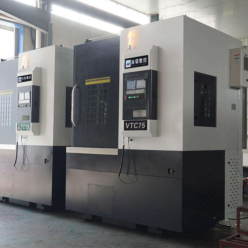
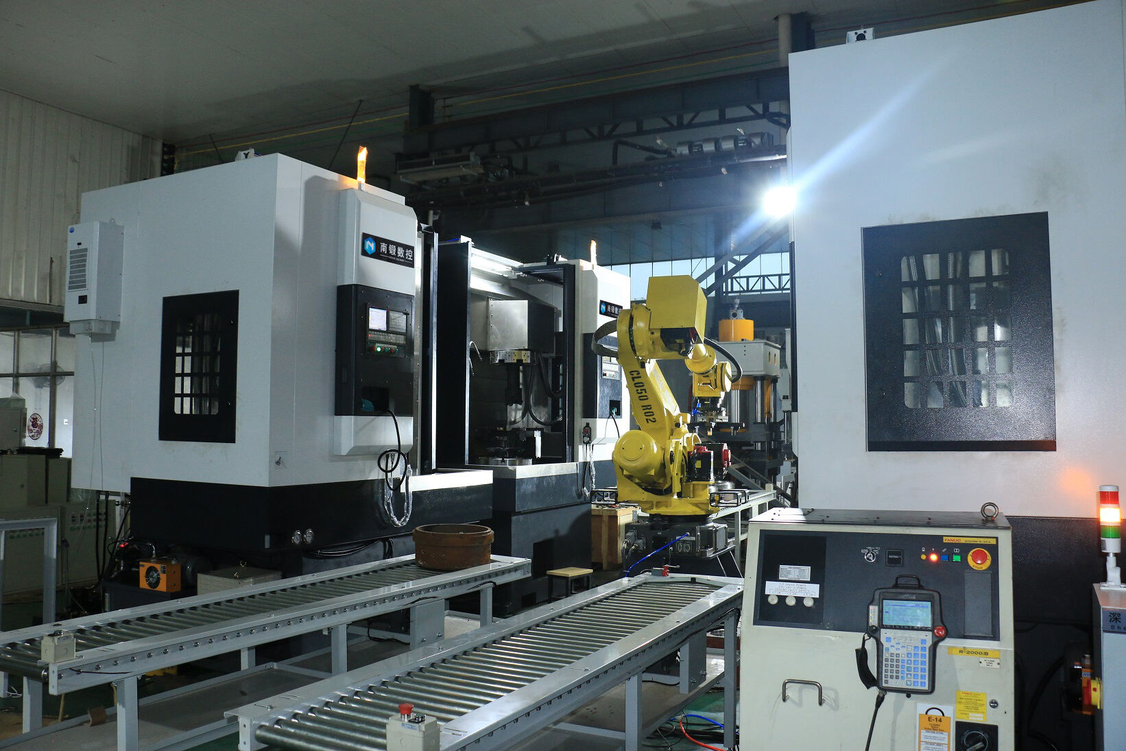
Nadun CNC Vertical Turning Lathe for cutting short shafts / disk parts / conical surfaces / internal external cylindrical surfaces
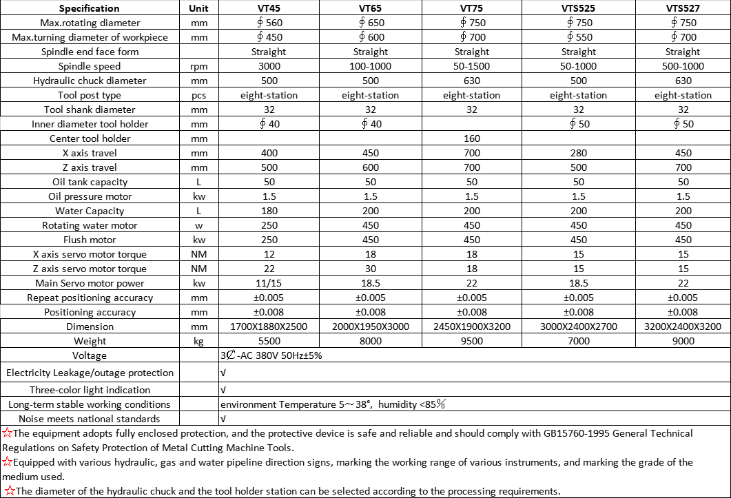
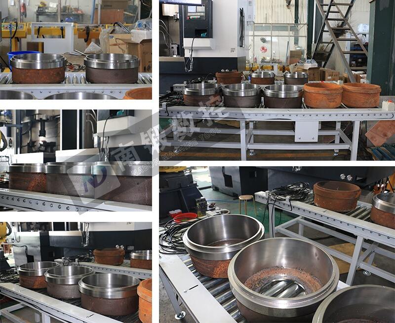
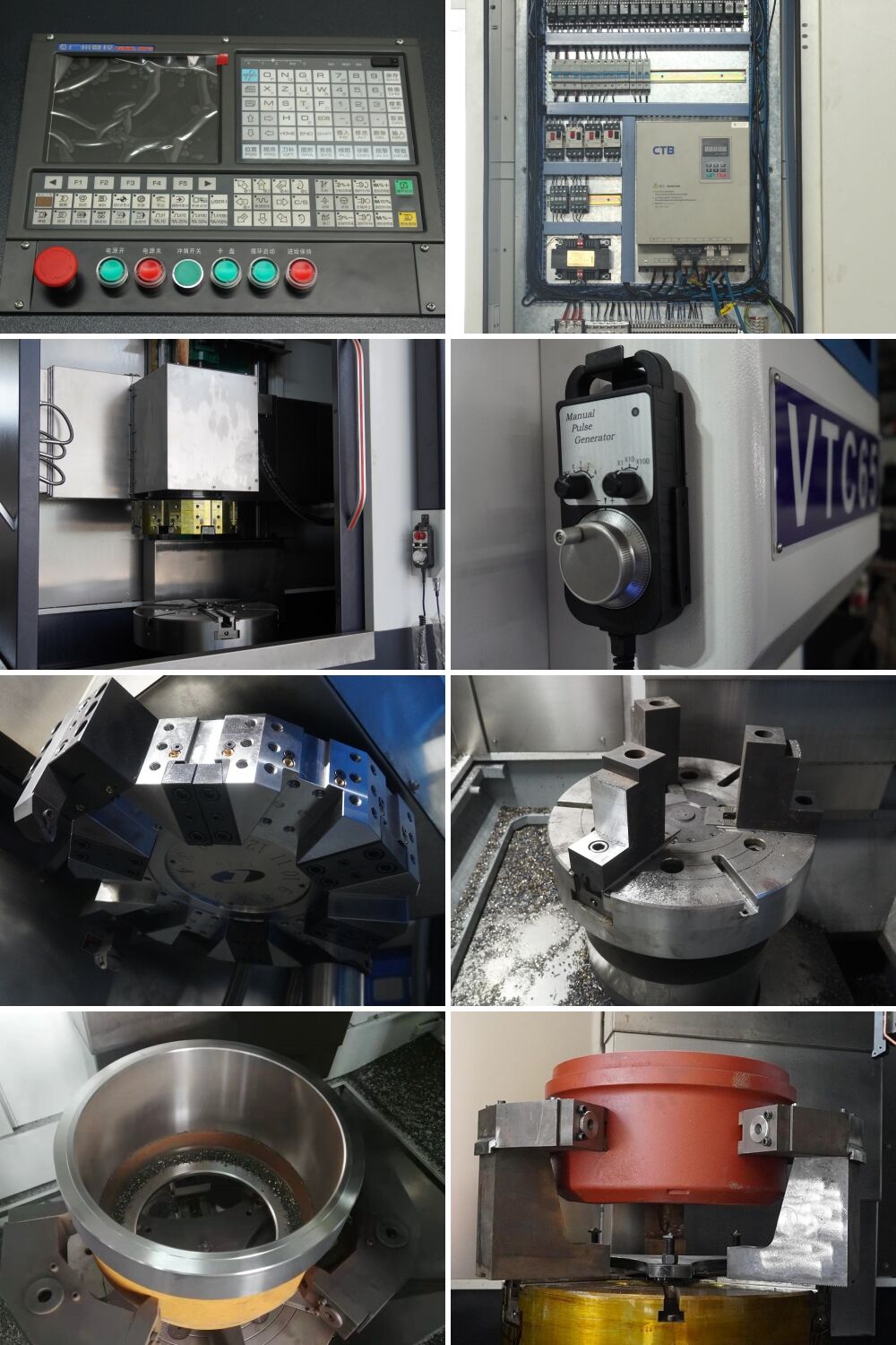
CNC Vertical lathes are primarily used for machining large, short, heavy workpieces' external cylindrical surfaces, end faces, conical surfaces, cylindrical holes, or conical holes. They can also be equipped with auxiliary devices for threading, spherical turning, profiling, milling, and grinding. The primary characteristic of vertical lathes is that the spindle is upright, with the worktable positioned in a horizontal plane. The workpiece is clamped on a large worktable driven by the spindle's rotational motion. Due to the workpiece being mounted on a horizontal worktable, clamping is relatively convenient. The quality of the workpiece and cutting forces are supported by the rotational guide rails between the worktable and base, reducing the load on the spindle and bearings, ensuring stable operation and maintaining machining accuracy over extended periods.
For more information about CNC vertical lathes, please contact us.
1. The base, column and sliding seat are all made of high-grade gray cast iron and have been tempered. Ensure that the machine tool has highstrength and precision stability for long-term use.
2. The machine adopts roler-ype linear slides. it has super high rigidity and heavy load capacity. The positioning accuracy,oad-carrying capacity of vertical and horizontal feed movement are greatly improved.
3. The spindle pulley of the machine tol and the spindle CNC servo motor pulley are connected by a belt, and can be configured with 18.5Kw or2kw motors continuousiv variable speed,. and wide speed ranee. t can meet the difterent reauirements of the spindle speed for rough machiningand finishing of parts.
4.The vertical and horizontal feeds are controled by the servo motor automaticaly. There are protective devicesin both directions, and a loadbalancing mechanism is installed in the vertical direction, which reduces the load of the lead screw and greatly extends the ife cycle of the leadscrew.
5. Both ends of the ball screw in the vertical and horizontal directions of the machine tool are supported by special screw bearings, which greatly improves and guarantees the machining accuracy of the machine tool's parts.
6,The machine tool adoots an electric lubricating oil oump to automaticaly lubricate each part in an intermitent manner to ensure thelubrication of each guide rall pair and ball screw pair. which can prolong the service life of each movement pair.
7. The tool post adopts horizontal or vertical multi-station CNC tool post, which has short tool change time and greatly improves work efficiency.
8. The upper end of the spindle can be equipped with a disc table or hydraulic chuck according to user requirements. The lower end of themain shaft can be equipped with a rotary oil cylinder, which is divided into singlepiston and double piston, The single piston cylinder can be used to control the tooling to compress the workoiece.or to control the hydraulic chuck. With dua-piton cylinders. one cylinder controls the hydraulchuck, and the other cylinder controls the tooling to compress the workpiece.
Functional characteristics
Spindle
The spindle's bearing adopts double-row roller bearings,and the axial direction adopts two way thrust angular contact ball bearings,whichcan provide a maximum axial load of 497KN.In order to obtain themaximum rigidity of the spindle,the contact area of the bearing reaches more than 98%,which ismuch higher than the industry regulations 85%,and the spindle diameter radial beat /end face jump are both within 0.003mm.Integral spindle unit,high rotation accuracy; imported linear roller guide rail,Pre-drawn screw support,taking into account cutting rigidity and positioning accuracy.
Spindle drive
The spindle drive is divided into a servo motor that directly drives the spindle through a timing belt to achievegreater torque output.
Axial feed
As a vertical axis,the Z axis bears greater load for a long time,and iseasier to wear than the parallel axis guide screw.TheZ-axis adopts a 55mm roller-type guide railwith a screw diameter of 50mm as standard equipment.In order to achievethe rigidity of the axial feed andthe maintenance of long-term accuracy.
Large stroke design
In order to satisfy the thin-walled deep hole processing represented by the brake hub,a composite toolbar is installed in the center of the turret,which can realize the tool change in the workpiece without retracting the tool,which can greatly improve the processing efficiency.It is used to process large and heavy workpieces with large diameter and short length and workpieces that are not easy to be clamped ona horizontal lathe.
Numerical control system
Commonly used numerical control system:
1.Domestic numerical control system:GSK,Chengdu,Guang Tai,Beijing,Kandi KND Huazhong numerical control system
2.Imported CNC system:SIEMENS CNC system in Germany,Mitsubishi in Japan. FANUC Fanuc,Japan


Our friendly team would love to hear from you!
Copyright © Nadun Machinery Manufacture Co.,Ltd. All Rights Reserved - Privacy Policy